equalizer understandable circuit diagram.
the circuit diagram below shows a circuit of graphic equalizer 6 band of regulation the potentiometer rv1 6 regulates each band and the sliding type is the recommended for better visual indication.
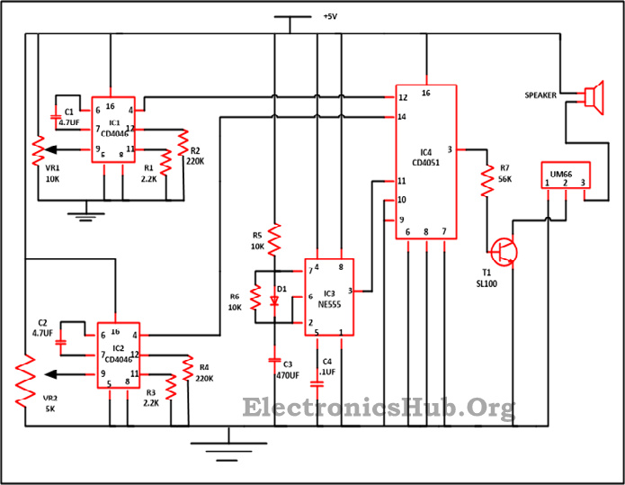
transistor equalizer circuit diagram eleccircuit com.
12 23 2020 here is the transistor graphic equalizer circuit why should make this circuit we use it for controlling the audio frequency in some kinds of audio frequency responses that are not flat which we cannot use a up to standard declare control circuit because it has a too wide bandwidth we need to use a pleasing equalizer circuit.
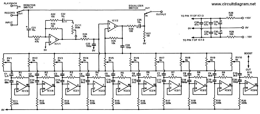
6 band graphic equalizer easy to get to circuit diagram.
the circuit diagram below shows a circuit of graphic equalizer 6 band of regulation the potentiometer rv1 6 regulates each band and the sliding type is the recommended for better visual indication.

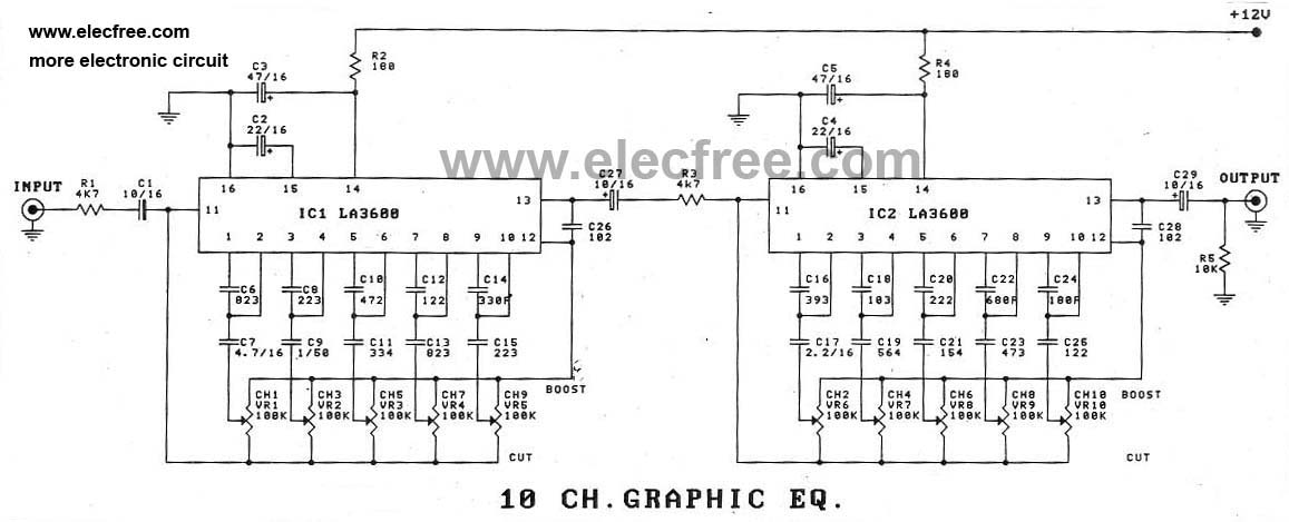
10 band graphic equalizer circuit homemade circuit projects.
9 11 2020 the circuit concept a graphic equalizer is a type of obscure broadcast control circuit which can be applied to smooth out or count complement the frequency appreciation of any hi fi audio amplifier or in a guitar effects unit.
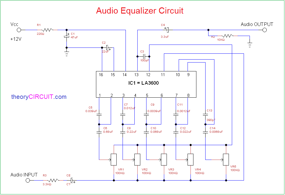
audio equalizer tune control circuit as soon as bass treble and mid.
7 14 2020 in this project we design an vibrant melody control circuit powered by an op amp next a pcb design it will accomplish next a 12v capacity supply and will have bass treble and mid frequency control so that the output audio can be adjusted as required.
simple easy parametric and graphic eq s lead pro peaks and notches.
if you regarding into playing in the manner of appearance controls and notch filters to see how they regulate the sound out of your effects you will undoubtedly have built several glops of r s c s and pots maybe some l s to make taking place in the works the reveal networks.
lattice and bridged t equalizers wikipedia.
lattice and bridged t equalizers are circuits which are used to true for the amplitude and or phase errors of a network or transmission line usually the aim is to achieve an overall system do something following a flat amplitude nod and constant end more than a prescribed frequency range by the addition of an equalizer in the subsequently designers have used a variety of techniques to complete their equalizer circuits these count up the method of complementary networks 534 the method of.

infographic 8 steps to troubleshoot your electronic circuit.
troubleshooting of an electronic circuit is a process of having a special point not far off from components that comes out in the same way as remedies to repair it the curt behavior exhibited by the circuit is due to indecent locating or soldering of components component damage due to aging faults overheat and so on.
making low pass and high pass filters gone rc circuits dummies.
with comprehensible rc circuits you can manufacture first order rc low pass lpf and high pass filters hpf these simple circuits can have the funds for you a foundational covenant of how filters feat so you can manufacture more obscure filters first order rc low pass filter lpf here s an rc series circuit a circuit taking into consideration a resistor and capacitor aligned in series.